Introduction
I should start off by saying that I’m a total newbie to the do-it-yourself electronics scene. I’m interested in this stuff but truth be told I build headphone amps because I want to use them. I doubt I’ll ever become one of those guys who has fifteen different amps of varying designs and application—but you never know what could happen. I’ve definitely been bitten with the obsession of building the best sounding amp possible for the application and money. I can see that it’s a slippery slope.
In the summer of 2003 after realizing that I spend all of my time at my desk at work (I was a software developer at Organic at the time), I decided to splurge and get a good pair of headphones. After listening to several, I decided on a pair of Grado headphones. These are terrific phones for anyone interested in perfectly reproduced reference-neutral sound. I bought the SR-225’s–basically they’re middle of the line phones. Apparently even their cheaper lines like the SR-80s are amazing, especially for the price.
I thoroughly enjoyed listening to all my old favs through the newly acquired detail of the Grados. I liked them so much that I started reading, and lo and behold, everyone was talking about how much better they sound with a headphone amplifier. My first question was “what the hell is a headphone amplifier”. In short, it’s a device that provides the exact power requirements and electronic environment headphones need to work to their full potential. Think of it this way: the average portable CD player has about 50 cents in parts dedicated to the headphone driver circuit. 50 cents + $300 for a pair of headphones = a bad match. Many manufacturers make commercial units, but since they are geared to the audio enthusiast or audiophile they cost big bucks. Grado themselves make one for their line of headphones called the RA1 but it costs hundreds of dollars. The kicker is that it contains maybe $10 in parts (plus the wicked looking mahogany case). Because of this price hike hundreds of people are building their own amps. Headwize is an excellent place for headphone enthusiasts to group and contains many many designs for do-it-yourself headphone amps for all applications and skill levels.
Prior to taking on this project I had built one other amp—a cmoy pocket headphone amp. This is an excellent little amp. Thanks to the excellent step by step instructions written by Tangent I managed to get my way through building it. It sounded terrific, a noticable improvement from what I had been hearing directly out of my headphone jack.
Sadly, I fried the op-amp in the Cmoy (the little chip inside that does all the work) after listening to it for 6 months. Refusing to go back to the headphone jack, I took it as an opportunity to build another amp—perhaps one a little more advanced.
Enter the Apheared 47 Headphone Amplifier
When browsing Headwize trying to find an amp that looked fun to build I found The Apheared 47 amp. It was designed specifically for Grado headphones which immediately sparked my interest.
Grados are different from most high-end headphones in that they have a relatively low impedance (32 Ohms). Most others are in the hundreds of Ohms. Top of the line Sennheisers run as high as 600 Ohms. This means that Grados require more current than most headphones, therefore, general purpose headphone amps can have trouble providing power that’s appropriate for Grados. This can change the sound quality rather than the volume—an important distinction. My Cmoy amp could drive the Grados plenty loud, but wasn’t providing optimal high current handling.
The Apheared 47 uses a two stage opamp approach that improves current handling. There are four opamps in the A47: two for the left ear and two for the right. The rest of the circuit is very similar to the Cmoy.
Gathering Info on the A47 Design
Before building anything I did a lot of reading on Headwize. Apheared had only provided a schematic of the amplifier circuit with no mention of power supply requirements etc. I posted a thread on headwize that got me started enough to build the new amp on a breadboard. When I couldn’t get this to work properly I posted another thread. This second thread produced tons of useful information about the power supply requirements and general design of the amp. Specifically, the Cmoy suffered from drift in the power supply that would cause the amp to become unstable and distort (this is probably what ultimately fried my Cmoy). This time around I wanted to make sure this couldn’t happen—especially since I was doubling the load on the power supply with two additional opamps. If you read the thread you can see the suggestions made. Basically, the resulting advice from the discussion was to add a TLE2426 and a BUF634 to the power circuit that nails the voltages to their desired values. This provides a nice stable platform for the amp circuit to operate on.
This solution had the added bonus of making the power supply so stable that I could use a noisy power source like a DC wall wart plug to power the amp. For the Cmoy, I had to use a 9V battery and had to charge it once a week. If I used the wall wart with the Cmoy it would cause the opamp to oscillate and therefore distort and heat up.
The Plans
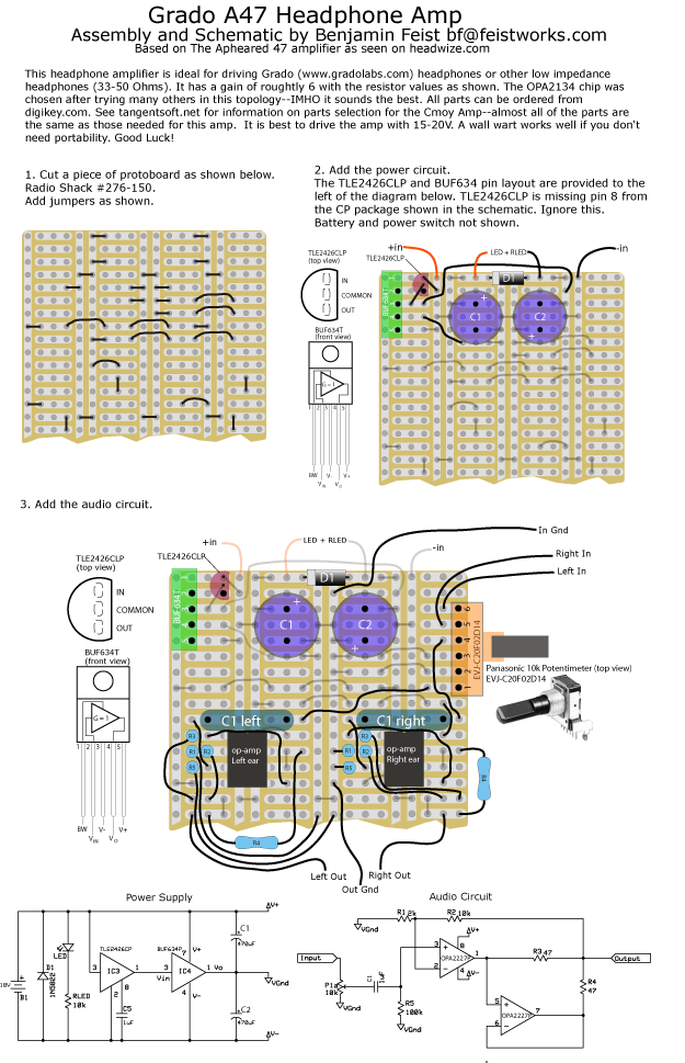
When I first began to approach the circuit layout on an actual circuit board, I found that I was completely lost. Tangent’s Cmoy instructions had been very clear as to where to place each component and jumper—this time around I had nothing but a power supply schematic and an amp circuit schematic. Some people suggested that I use graph paper to lay out the circuit. I tried this, but every time I had to move something there was a heck of a lot of erasing involved. Each time I updated the layout on the paper I became less sure that it would actually work.
I broke down and postponed the build (yet another week without tunes at work), and decided to make plans for this amp similar to the plans Tangent made for the Cmoy. The result is below.
You can download it here in PDF format for printing. [Download]
I followed the instructions that I had written when building the amp and it came out fine (once I found the jumpers I had forgotten to solder). Unfortunately I didn’t take any pictures as I was building. It would have just looked like an amateur soldering mess anyway.
The Case
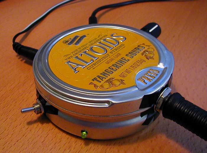
I managed to jam the resulting board into a round Altoids mint tin. Very cool looking if I do say so myself.
It was totally unnecessary to put the circuit into such a small case. I did it mainly because I thought it would look cool. I did manage to break the amp four times before successfully getting it into the Tangerine Sours tin. I cut holes in the sides of the tin using a pair of wire cutters, a drill, and a dremel. I covered the inside and the holes with black electrical tape. Strangely, this tin was conducting power from the DC plug into the body of the case where my Cmoy in the other Altoids tin didn’t. Both are made of conductive metal so I’m not sure what was happening there. Black tape through the holes solved the problem.
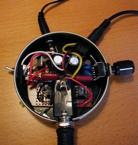
The guts of the amp. Note that I managed to shove a 1/4″ jack into the case. Many people use a 1/8″ jack to save space, but I wanted the grados plug in directly without an adapter.
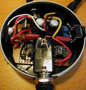
A closeup of the guts. Notice the OPA2134 opamp chip. I also tried the OPA2132, OPA2227, and OPA2228. Any dual opamp with the same pin assignments will fit.
Anyway, if you decide to build this amp I hope I’ve provided some info that will make it easier on you than it was me. Best of luck! If you own Grado headphones I think you’ll be happy with the improved performance. Oh, a word of advice: it’s always a good idea to try your amp with a pair of crappy headphones before plugging in your $200+ grados—I’ve heard stories.
Email me if you have any questions/comments.

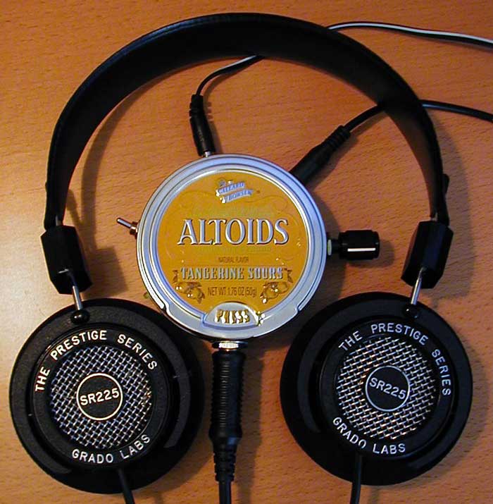
I agree that the Grado SR-225’s work marvelously with a headphone amp. For yours, is there a pcb available?
Myself I’ve got 4 different headphone amps and the SR-225s never fail to please.
Take Care—
Jerry
I’m sorry there’s no PCB available, just the DIY method I outline in the PDF.
I am building this amp for my Grado SR80s and just want to know the specs on the wall wart that you used, thanks, Steve.
Any 15V-20V DC wall wart works fine. Anything over 200mA should work fine.
See this;
http://www.ebay.com/itm/Headphone-Amplifier-47-AMP-Audio-Amplifier-DIY-Kits-NE5532-OP-AMP-Module/252487814833?_trksid=p2047675.c100005.m1851&_trkparms=aid%3D222007%26algo%3DSIC.MBE%26ao%3D2%26asc%3D38530%26meid%3D1069e66a9af54ac8b1a5726c3fbd9e06%26pid%3D100005%26rk%3D1%26rkt%3D6%26sd%3D181832692825
‘should work with Fostex 600 which are 25ohms and need current….
Thanks for impressions, good job sir 🙂
@MKING:
I built an amplifier with NE5532 based on schematic that i seen on ebay.
It works with my 32 Ohms headphones.
I use it with rechargeable Li-ion batteries instead of power transformer.
Would a 300 ohm headphone work with this amp?
No, this amp is specifically designed for 32 Ohm.
Do you know of any amp kit that would suit a 300 ohm load?
I’d like to get an idea of actual gain of an amp like this (in particular the NE5532 since that is the kit I am considering). Right now, I use a Fiio E5 which has 100mW (32ohms Load). I was considering the A3 which has more than 2x that but a much higher price tag. Would the 5532 based amp offer double the gain my E5 does?