Introduction
I encountered a problem with a bunch of 3COM HomeConnect 10/100 hubs that my employer bought to use around the office whenever we were short on LAN drops. They seemed like a good choice–small, fanless, 100mbps capable, beige… Then, one by one they started frying themselves.
The collision light would constantly flash even if nothing was connected to it, and little or no (usually no) data would get through. A reset did squat to fix the problem but leaving it off for a few hours would sometimes get it working again for 5 or 10 minutes only to result in the same problem.
3Com was (and is) absolutely no help. Their own tech note on the problem says to power cycle the thing! That’s like GE telling you to check the light-switch as the only solution to a burned out bulb.
3Com’s tech note is now a broken link (that used to require you to sign up), here is the key content from their tech note before it vanished:
SolutionID:
2.0.79416831.3330656
Title: 3C19261 – Collision LED is on with nothing plugged in
|
The Cause
Inspired by my success fixing yet another busted piece of equipment, my Apple Airport (thanks to this wicked site), I felt fearless and cracked the case on one of these babies. Lo and behold, the same problem was immediately evident as was the problem on the Airport power supply–blown capacitors.
Check out this related Slashdot article on the subject of crap capacitors.
Update: Just read this recent and somewhat hilarious story that may help to explain why so many capacitors may have been failing lately.
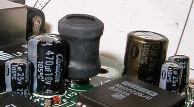
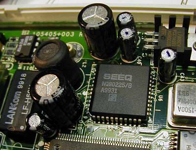
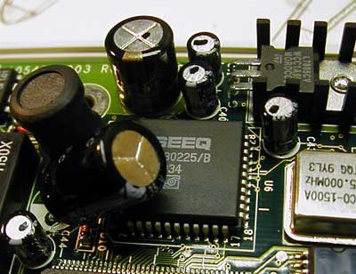
If you look closely at the picture above, the 470µF 16V capacitor (2nd from the left) has a slightly crowned or “popped” top. This is a sign of capacitor failure. This can happen for a number of reasons, overheating being one. I figured a good start would be replacing these blown capacitors. In some of the other hubs that were dead, the 470µF 24V capacitor was also blown (the big one 3rd from the right).
What You’ll Need
Disclaimer – opening your hubs will void your warranty, and greatly increase your chance of hurting yourself, someone else, and the hub. By reading further you agree that anything you do to your hub that is described in this article or otherwise is your own fault and your own responsibility. I’ve only written this to show people what I did. If your hub is under warranty, call 3Com and get them to fix it (if you can).
Run down to your local electronics store, and find some replacement caps. The caps that blew were rated to 105ºC. This obviously wasn’t good enough due to the knucklehead design of the casing and the mammoth amount of heat this board generates. I couldn’t find any caps rated for a higher temperature at my local shop, so I opted for a larger voltage rating. In general you can use a capacitor of a higher voltage rating as long as the capacitance rating remains the same.
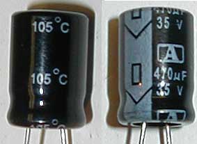
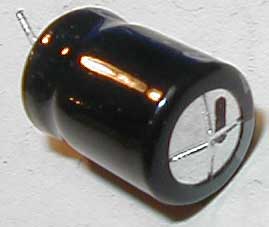
Above is a picture of the 470µF 35V caps I managed to find that are rated to 105ºC. They were 35¢ each (Canadian). They’re a bit big, but can be jammed in to fit where the 16V one was. Strangely, the 35V fit in the 16V slot in one of the hubs, but not in the other three I had to repair.
So to summarize, you need to replace two capacitors:
– One 470µF 16V
– One 470µF 25V
For both of these, I used 470µF 35V replacement caps.
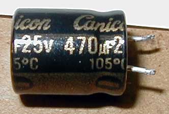
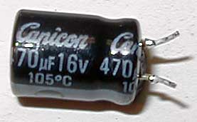
Here are pictures of the two caps that need to be replaced. I have no idea who “Canicon” is, a google search brings up squat–perhaps for a reason.
The Fix
Ground yourself! You’re about to open an electronic device. Touch something large and metal before touching the board to be sure you have no static on your hands. Avoid touching the pins of the board, avoid handling the board unless you have to, avoid touching anything! Unplug the hub! (does that have to be said?)
Open the case with a flathead screwdriver (see if you can find one as rusty as mine). Place it as shown in the pictures below and twist the case open–for style points see how badly you can mangle the beige case.
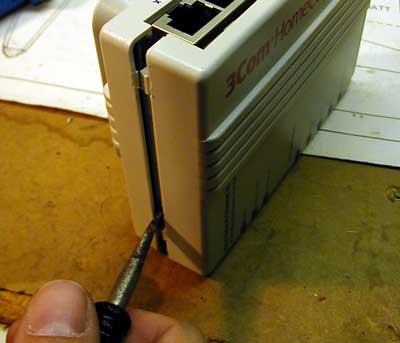
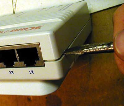
With a few twists it’ll pop open.
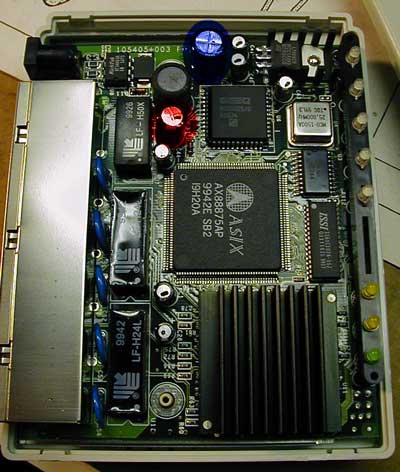
Above is a shot of the opened hub. The two circles mark the caps that I found needed to be replaced. Red for the 16V cap, and blue for the 25V cap. Check all the other caps thoroughly for any sign of being popped; the two I highlited in the picture were the only two I saw a problem with in any of the four hubs I repaired. The heat sink at the bottom right of the image gets very hot for some reason–blame it for the failed caps. If 3Com had a half-decent thermal dynamics engineer on staff this would never have happened.
The two images above show one hub that had a bad 16V and a good 25V. Look closely and you can see why the 16V is bad: rounded top.
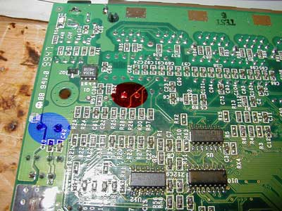
The above shot is the bottom of the board with the leads of the same two caps highlited. Capacitors have two leads; identify the leads of the capacitors that have blown on your hub.
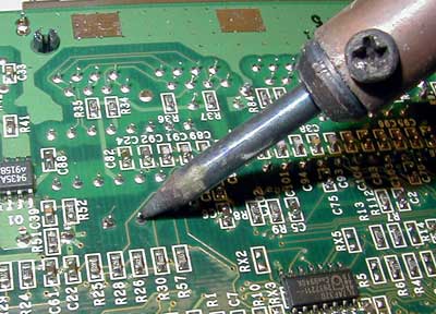
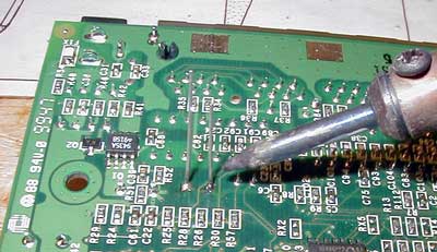
With a 25-35W soldering iron, heat the leads of the blown cap while pulling the cap from the other side of the board. With a bit of work it should slowly come loose one leg at a time until it pops out. In the shot above I’m desoldering the 16V cap.
These two shots show a popped 16V cap. Notice how it’s all bulged out at the top and the bottom is deformed. Sometimes a blown cap will hiss when power is applied to it, but not always. This is the cap that had failed in all four hubs I fixed. The 25V had failed in only one of the four hubs I fixed. You’ll have to check all the caps in your hub yourself.
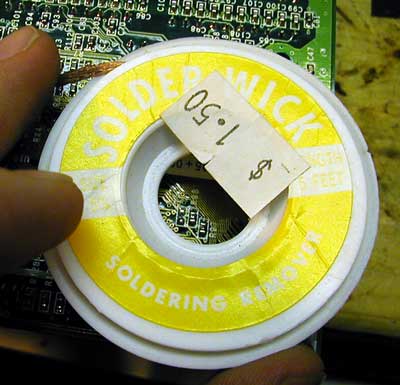
Remove all the solder from around the holes the old cap was in. The best way to do this is to heat the solder with the iron from the other side of the board and use a “solder sucker” like the one shown above. Another way is to heat some soldering braid (above right) over the holes to wick the solder from the board.
You should have two almost-clean holes before you solder the new caps in. Old solder or dirt can result in a cold solder joint. Cold solder joints are bad for various reasons. Your solder connections should be shiny and not globby. More soldering help can be found at my favorite DIY headphone amp site, and here. You could do your PhD on soldering if you were so inclined.
Place the new capacitors in place however you can get them to fit. Electrolytic capacitors (like the ones we’re using) are polarized–that is, you have to make sure you put them in the right way. There should be a grey bar running down one side with a “-” in it (look closely at the picture above). This is the negative leg of the cap. Be sure to put it in the same way the old one came out or you could damage the whole board.
One of the hubs I fixed had room for the 35V replacement in the place where the 16V was (above left), but the other three had no room at all and I had to leave the legs a bit longer and bend the cap over so the case of the hub would go back on (above right). The above left shot shows both the 16V and the 25V replaced with two 35V caps.
Turn the board over and apply a tiny bit of soldering paste to the legs and holes–rosin is the best for electronics. The idea is to get the solder to wick into the holes for a solid connection. Using an eutectic solder (Sn63/Pb37) can help to ensure a solid joint. The most common solder is 60/40 and will work fine for the tiny amount of soldering we’re doing here.
From Headwize: “Use an eutectic solder! An eutectic solder does not go through a pasty state. Instead, it goes from liquid to solid instantly! Results? You get a very tight, fine-grained solder joint. Why is this important? The finer the grain of the solder, the stronger the joint and the more it is able to conduct electricity. Thus, the tiny movements of your hand does NOT affect an eutectic solder. The solidification of the solder is too fast.”
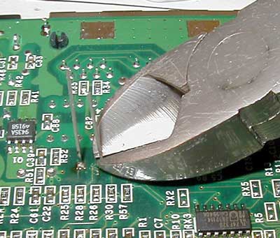
Clip off the legs close to the board without cutting the solder joint.
Plug in the hub to see if you get a power light. If you don’t, you’ve done something wrong–unplug the power immediately and check that you haven’t reversed a cap or done some other damage.
Voila!
You’re done. It might be a good idea to drill a few holes in the ugly case to help with ventillation so you don’t wind up doing this all over again. Put the board back in the case.
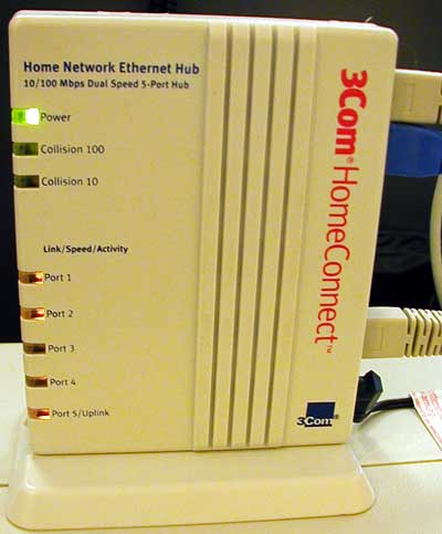
Also, when operating the hub, sit it in its upright position (as shown in the picture below). This will allow the heat from that heat sink to roll out the top without going past the caps.
Here’s a finished, working hub! Note the lack of a constantly blinking collision light (yay).
Good luck!

